Thermal Equipments & Packages
Shell & Tube Heat Exchangers
Heat exchangers are equipment used for transfer of heat.
Paramount designs and manufactures shell and tube heat exchangers for the refinery, petrochemical, fertilizer & chemical industries.
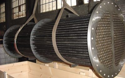
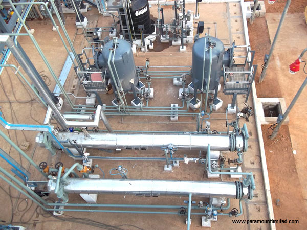
Following services are provided by Paramount on heat exchanger design / engineering.
- Develop new design using HTRI software which facilitates optimum and reliable design
- Simulate or rate existing exchangers for checking adequacy for new operating conditions
- Study the exchangers for fouling or malfunctioning
- Carry out vibration analysis for newly designed exchangers or existing, exchangers which are experiencing problem of vibration
- Develop mechanical design and fabrication drawings as per ASME/ TEMA
Paramount has ASME approved shop for the manufacture of shell & tube heat exchangers.
Multiple Effect Evaporator System
Evaporator differs from crystallizers in which evaporation is concerned with concentrating a solution rather than producing or building crystals. Evaporation is distinguished from drying giving always liquid residue.
Paramount offer multiple effect evaporator as stand alone process unit and also for treatment of RO concentrates to achieve zero liquid discharge in Wastewater treatment plant.
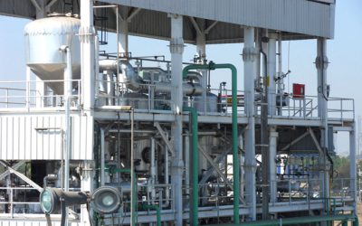
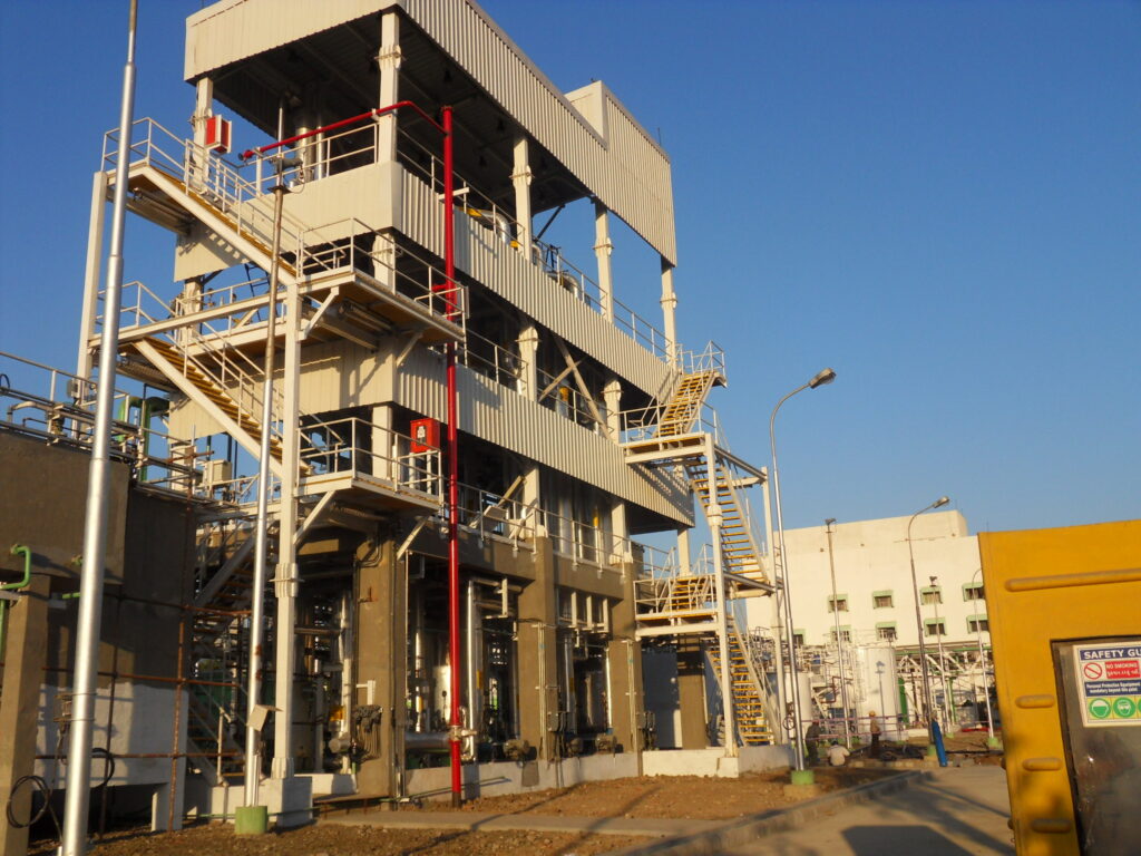
Paramount designs and supplies a wide range of Evaporator such as single effect and multiple effects as per the needs of various process industries which are as follows:
- Vertical Tube Evaporator
o Falling Film
o Rising Film - Forced Circulation Evaporator
- Horizontal Tube Evaporator
- Plate Type Evaporator
- Natural Circulation Evaporator
- Flash Evaporator
Paramount offers superior technology in the field of Multiple effect evaporator with specific thrust on Heat transfer, Vapor liquid separation & efficient utilization of energy.
The superior expertise of Paramount in Evaporation has following features:
• Pure Condensate recoveries
• Higher Salt recoveries
• Higher thermal efficiencies by employing minimum scope of steam
• Minimum Operating cost by using Mechanical Vapour Recompression (MVR) & Thermal Vapour Recompression (TVR)
• Optimum Thermal design using software like HTRI & Aspen
Paramount offers Application for Evaporator in following Industries:
• Chemical industries
• Pharmaceutical
• Biotechnology
• Food & Dairy
• Beverage industries
• Environmental applications
Waste Heat based Evaporation System
Industrial processes like Reverse Osmosis plant generate liquid effluent containing a high amount of inorganic soluble salts. Conventionally, wastewater containing high soluble impurities (dissolved solids) cannot be disposed of to water bodies. Methodologies followed are
- Conventional methods employ the high dissolved solids effluent is mixed with other dilute wastewater streams, before disposal, to meet disposal standards.
- In many cases, the soluble impurities are precipitated by using chemicals.
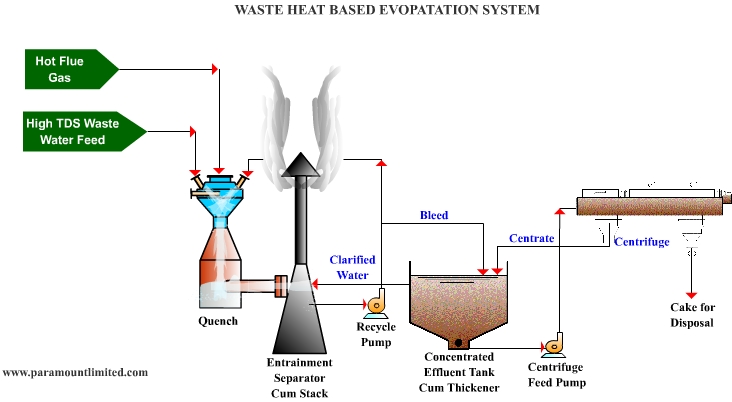
To achieve the concept of “zero discharge”, the wastewater with high dissolved solids is treated using evaporator / RO technology where the liquid fraction of the wastewater is recovered in the form of water, which may be reused, and impurities present in the wastewater are collected separately as inert solids/ concentrate. Even though the evaporation/ RO technology provides a proven remedy for treatment of wastewater with high dissolved solids, it is used on a limited scale because of:
• High cost of equipment
• High cost of energy for its operation
• Complex operation requiring skilled manpower and major plant automation
Paramount provides an innovative concept of using “Quench”, a proprietary compact design for evaporating water from wastewater containing a high level of dissolved solids (50,000-55,000 ppm). This concept works to optimize and utilize the waste heat of the flue gases generated from the power plant/ incinerator units.
In normal practice, a quench is used to cool the hot gas by having a direct contact water spray to reduce the gas temperature. Water is evaporated and converted to steam. This concept is based on evaporative cooling. The gas is further treated, as the case may be, depending upon the process. This concept of evaporative cooling is utilized from a different perspective (i.e. to evaporate the water using the waste heat rather than the conventional concept of cooling the gases with water).
This would result in the concentration of wastewater in the form of the slurry, containing suspended solids, generated due to the presence of high TDS and evaporation of water, which can be centrifuged to form a disposable cake. The centrate from the centrifuge is sent back to the quenching system for further evaporation. The cooled flue gases with water vapours can be discharged to the atmosphere through a stack.
This innovative concept was also presented to the Ministry of Environment and Forest (MOEF) and has been accepted.
This approach also helps to achieve a reduction in the initial cost of the plant including extremely low operating cost.
Comparison of Waste heat based Evaporator System with conventional Evaporator (Multiple effect) systems:
Sr. No. | Features | Evaporator System | Quench System |
1 | Type of System | Multiple Effect Evaporator using steam as source of Heat | Flue Gas Quenching System to evaporate the water using waste heat in flue gases |
2 | Type of Operation | Complicated operation as it requires operation of lot of pumps, reactors and is highly instrumented | Very simple to operate as only four simple equipment needs operation |
3 | Operating Personal Requirement | Highly skilled operating staff conversant with process plant operation | Skilled operating staff with normal operating skills |
4 | Flexibility W.R.T. To Turn Down and Change in Effluent Characteristics | Less flexibility as the plant requires lot of controls due to change in effluent characteristics and turn down | No change in plant operating parameters are required even if there is a major change in plant capacity and effluent characteristics |
5 | Flue Requirement | Envisages Installations of a new Boiler for meeting system’s steam requirement which would use fuel for steam production | Steam Boiler is not required and hence does not envisage burning of fuel |
6 | Reliability W.R.T. | Good | Very High |
7 | Turn Down Possible | Up to 30% max. | As low as 10% |
8 | Power requirement | 15 – 17 KW/M3 | 1.5 – 1.6 KW/M3 |
9 | Steam Requirement | 300 – 350 kgs/m3 | Not required |
10 | Cooling Water Requirement | Yes | No |
11 | Space Requirement | More | Less |
12 | Quality of End Product (Cake) Generated | Cake with 75 – 80% solids | Comparable |
13 | Any other Salient Feature | High Maintenance Cost due to cleaning requirement of scales formed on tubes | Very low maintenance cost due to less number of equipment which are simple to operate and does not require de-scaling |
Surface Condensor
The main Application of heat transfer mechanisms in a surface condenser is the condensing of saturated steam or Vapour on the outside of the tubes of the condenser which is done by circulating Chilled water or Cooling water inside the tubes of the condenser.
Due to the fact that a surface condenser operates under vacuum, non-condensable gases will migrate towards the condenser. The non-condensable gases consist of mostly air that has leaked into the cycle from components that are operating below atmospheric pressure.
These gases can also result from caused by the decomposition of water into oxygen and hydrogen by thermal or chemical reactions.
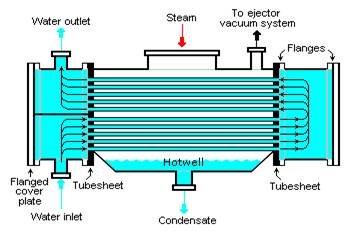
These gases must be vented from the condenser for the following reasons:
The gases will increase the operating pressure of the condenser. Since the total pressure of the condenser will be the sum of partial pressures of the steam and the gases as more gas is leaked into the system, the condenser pressure will rise. This rise in pressure will decrease the turbine output and efficiency.
- The gases will blanket the outer surface of the tubes. This will severely decrease the heat transfer of the steam to the circulating water. Again, the pressure in the condenser will increase.
- The corrosiveness of the condensate in the condenser increases as the oxygen content increases. Oxygen causes corrosion, mostly in the steam generator. Thus, these gases must be removed in order to extend the life of cycle components.
Surface Condensers prima facie are the generalized terms of a Water Cooled Shell and Tube Type Heat Exchangers that will utilize the heat of a motive liquid or gas to cool the receptive water, or in other words cool the flowing liquid.
Disposal of contaminated water is of growing concern in process operations. Where an ejector system is drawing in contaminants, a condenser that discharges directly to the drain may not be used. For such applications, ejectors using surface condensers are used. The surface condenser prevents discharge to the drain and permits recovery or treatment of undesirable wastes.
A steam jet ejector system with surface condensers normally requires more motive steam and condensing water than the one with direct contact condensers, and is the most expensive.
Key Advantages :
• Decades of design and manufacturing experience
• Compliance with HEI, ASME, PED and other design codes and engineering standards as per project requirements
• Wide range of sizes
• Experience to handle exotic and optional materials and configurations
• Provides individual equipment and consolidated packages
• Erection and Commissioning assistance and service
Thermosyphon Reboilers
Thermosyphon reboilers require pumping of the column bottoms liquid into the reboiler. Natural circulation is obtained by using the density difference between the reboiler inlet column bottoms liquid and the reboiler outlet liquid-vapor mixture to provide sufficient liquid head to deliver the tower bottoms into the reboiler. Thermosyphon reboilers are more complex than kettle reboilers and require more attention from the plant operators. There are many types of thermosyphon reboilers including vertical, horizontal, once-through or recirculating.
Thermosyphon reboilers play a wide role in the chemical industry, which provides a simple, low maintenance design for distillation tower reboiler system. The thermosyphon reboiler contains the two endearing qualities of the evaporator, namely mechanical simplicity and operation in the nucleate boiling regime with its attractive high fluxes. These reboilers require rational design procedure as several flow patterns manifests during the heat transfer to a flowing two phase boiling mixture, which in-turn depends on upon the flow rates, physical properties of the components, pipe diameter and orientation. The circulation rate, heat-transfer rate and pressure drop all are interrelated, and hence, iterative design procedures must be used.
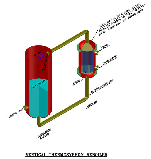
Table 1: Advantages and Disadvantages of thermosyphon reboiler
Advantages:
• Cheapest reboiler installation in terms of capital and operating cost
• Permits simple, compact piping arrangement
• Provides excellent thermal performance
Disadvantages:
• Not suitable for viscous or solid bearing fluids
• More heat transfer area required for vacuum operation
• Not specified for pressure below 0.3 bar
• Column base must be elevated to provide the hydrostatic head required for the thermosyphon effect.
• This increases the cost of the column supporting structure.
Features of Construction
In thermosyphon reboilers, performance is determined by the interrelated thermal and hydraulic characteristics, of the reboiler and the interconnecting piping. Circulation is established through the reboiler by the difference between the hydraulic head of the liquid in the column and of the two phase mixture in the reboiler. Raising the liquid level in the column, relative to the reboiler increases this difference in hydrostatic head and thus increases the rate at which the fluid to be vaporized flows through the reboiler.
Falling Film Evaporators
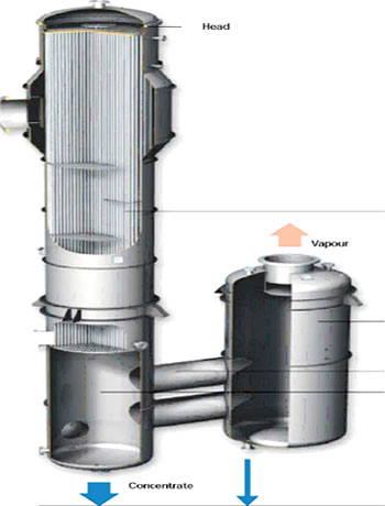
The Falling Film Evaporators can be operated with a low temperature difference and since the product residence time is very less, they are best suited for liquids which are temperature sensitive, have a high rate of specific heat transfer, particularly for non-crystalline solutions. Having low liquid holding volumes, the falling film evaporators are very easy to operate, clean and are extremely sturdy, thus the most frequently used types.
Caution must be used to ensure a continuous film wetting rate and to prevent nucleate boiling, otherwise the rate of heat transfer will fall off dramatically, and the rate of fouling on the heat transfer surface will increase.
In falling film evaporators the liquid product (A) usually enters the evaporator at the head (1) of the evaporator. In the head, the product is evenly distributed into the heating tubes. A thin film enters the heating tube are it flows downwards at boiling temperature and is partially evaporated. In most cases steam (D) is used for heating the evaporator. The product and the vapor both flow downwards in a parallel flow. This gravity-induced downward movement is increasingly augmented by the co-current vapor flow. The separation of the concentrated product (C) form its vapor (B) is undergoing in the lower part of the heat exchanger (3) and the separator (5)
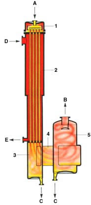
A: Product
B: Vapor
C: Concentrate
D: Heating Steam
E: Condensate
1: Head
2: Calandria
3: Calandria, Lower part
4: Mixing Channel
5: Vapor Separator
Falling film evaporators can be operated with very low temperature differences between the heating media and the boiling liquid, and they also have very short product contact times, typically just a few seconds per pass. These characteristics make the falling film evaporator particularly suitable for heat-sensitive products, and it is today the most frequently used type of evaporator.
Falling film evaporators are used extensively in chemical process industry, food and paper industry. Due to the absence of static head effect caused by liquid column as in other types of evaporators, evaporation can take place at very small effective mean temperature differences. The temperature difference is typically between 3 – 8C. This is significantly less than in other devices used for evaporation, e.g. forced reboilers or kettle evaporators, here the effective mean temperature difference is between 15 a 30C. The film heat transfer coefficients are in general high and characterised by surface boiling.
The absence of hydrostatic head allows this type of evaporator to operate at very low absolute pressures.
Product residence time can be very short, especially in one through the operation. This characteristic of short retention time low operation pressure and small required effective mean temperature differences makes this type of evaporator particularly suitable for concentration of heat sensitive liquids. The absence of nucleate boiling under normal operation conditions and low temperature differences reduces also possible fouling tendencies.
The flow pattern can be characterised as a liquid annulus with vapour core.
Conclusion:
- In general very high heat transfer coefficients, which can be considerably lower in systems with viscous mixtures.
- Very short liquid residence time in tubes, therefore, low liquid hold-up and inventory
- Small effective mean temperature differences, where evaporation takes place at the liquid surface. In general, it is recommended to avoid nucleate boiling (fouling)
- Pressure drop in tubes is often negligible, therefore, only in vacuum applications the calculated pressure drop has to be taken into account
- Falling Film Evaporators can be operated at very low absolute pressures, they can be used at absolute pressures approaching the hydrostatic head of film thickness
Typical applications :
- Distillery stillage
- Yeast effluent
- Grain wet milling
- Brine concentration
- Abattoir effluents
- Gelatinous wastes
- Black liquor
- Textile industry
- Wool washing effluents
- Oil emulsions treatment
- Pickling bath recovery
- Effluent from chemical reactors and storage tank cleaning
- Ammonium nitrate polluted condensates from reactors
- White waters (waters containing paraffin)
MEE Forced Circulation
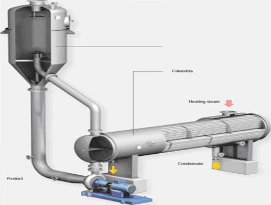
Forced Circulation Evaporators are normally used for liquids which are prone to fouling, scaling, and crystallizing or for those which are inversely soluble or while concentrating thermally de-gradable materials. Here high re-circulation rate allows high liquor velocities through the tubes which help to minimize the buildup of deposits or crystals along the heating surface. The universal type, preferably used for concentration of solutions containing encrusting substances, hardening agents and un-dissolved solids, and for viscose solutions; also suitable for evaporative crystallization.
The liquid is circulated through the calandria by means of a circulation pump, where it is superheated at an elevated pressure, higher than its normal boiling pressure. Since liquid circulation is maintained, the flow velocity in the tubes and the liquid temperature can be controlled to suit the product requirements independently of the pre-selected temperature difference.
Energy Efficiency:
Energy Efficiency of Paramount Evaporators and Crystallizers is a crucial consideration during the design of each customer’s specific application. Energy efficient systems utilize waste heat, multiple effects, mechanical vapour recompression (MVR) and / or thermal vapour recompression (TVR).
Multiple Effect Operation :
The evaporation duty is separated into stages operating at different temperatures. External heat drives the first effect of the evaporator, with subsequent effects being driven by vapor generated from the previous higher temperature effect. Product may be passed through the evaporator in forward, back or mixed flow configurations. Additional efficiency is achieved with the use of regenerative heaters, condensate heaters, and vapour heaters.
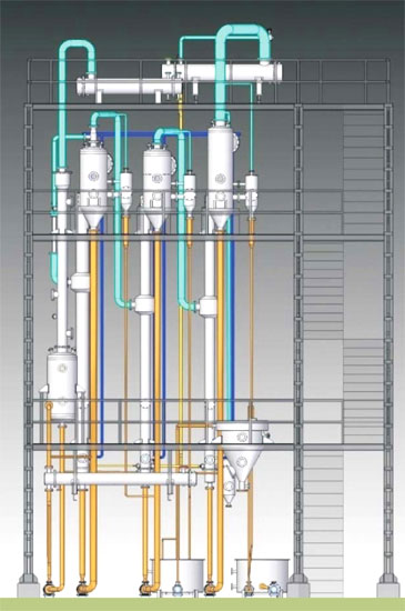
Thermal Vapour Recompression, TVR :
Multiple effect evaporation plants save steam by repeatedly using the same quantity of heat from effect to effect. The vapours from the first effect are compressed to a higher pressure by the thermocompressor, and these compressed vapours are the heating medium for the subsequent effect. Vapours from the final effect are condensed, heat is recovered and supplemented by the cooling water if required.
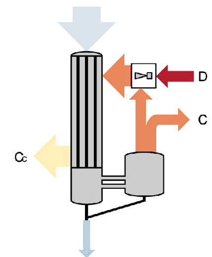
Mechanical Vapour Recompression, MVR:
MVR technology yields the greatest energy efficiency for an evaporator and requires low cooling water. An MVR evaporator may be coupled with TVR and multiple effects.
Evaporation plants with mechanical vapour recompressors normally require very low live steam and shifts the necessary energy to electric energy.
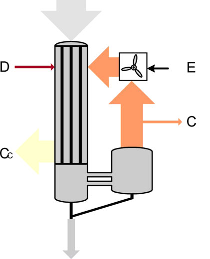
MVR can be either high pressure fans or centrifugal compressor types depending on the application.Single-effect centrifugal compressors are frequently used. For high pressure increases, multi-stage compressors are provided. To supply the power to the compressor, either electric power or combustion engines are used where heat is available from the cooling water and exhaust gases. If high pressure steam is available, a steam turbine may be installed for high total energy efficiency.
Fields of application :
Liquids with a high tendency for fouling, highly viscous liquids, as the high concentration step in multiple-effect evaporation plants.Forced circulation evaporators are optimally suited as crystallising evaporators for saline solutions.
FEATURES OF COMP FORCED CIRCULATION EVAPORATORS –
• Suitable for a widest variety of evaporator applications.
• Ideal for crystallizing operation.
• High heat transfer coefficients.
• Positive circulation.
• Freedom from salting, scaling and fouling.
• Suitable for corrosive and viscous solutions.
CRITICAL DESIGN FEATURES OF FORCED CIRCULATION EVAPORATORS –
• Optimum tube velocities
• Type of vapour head used with the forced circulation evaporators is chosen to suit the product characteristics.
TYPICAL APPLICATIONS –
• Effluent Treatments Plants
• Chemical Industry
• Salt Solutions
These shell and tube type evaporators outperform other tubular evaporators when used for water with dissolved salts or organics with a tendency to foul the evaporator tubes.
How they work :
This is a tubular evaporator having heating media on the shell side and the process liquid in the tubes. It has circulation loop equipped with high flow circulation pump.
The feed is introduced into the loop at the bottom. The high flow recirculation pump (Axial Flow Pump) forces the liquid through tubes. It picks up the heat from the shell side steam and flashes in the separator. The flashed vapour moves upward to vapour nozzle of the separator while the concentrate flows down to concentrate nozzle. The concentrate is re-circulated in the loop with high flow. A part of concentrate overflows out from the separator. The liquid height is engineered to avoid the nucleate boiling within evaporator tube bundle. The high flow circulation helps solids to remain in suspension and suppresses fouling.
Features :
• Reduced scaling, ideal for materials with precipitation or crystallization tendency
• Concentration values more than the limits of conventional tubular evaporators when handling feed with dissolved salts
• Multiple effect arrangement provides steam economy
• Equipped with axial flow pumps having high capacity with minimum power
Applications :
• Pre-concentration of scale prone liquids before drying
• Evaporative crystallization
• Wastewater concentration for volume reduction
• Concentration of organic and inorganic salt solutions
Agitated Thin Film Dryer (ATFD)
Agitated thin film evaporators and dryers are used to concentrate, refine or recover a valuable product through distillation or similar thermal separation processes. Due to its inherent design features, it is ideal for thermal treatment of solutions and heat sensitive products, where reduced operating temperatures and vacuum operating pressures are desirable.
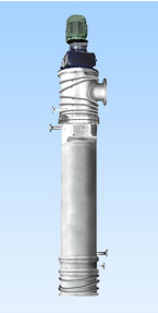
The typical agitated thin film evaporator consists of a tubular heat transfer area with an external heating jacket and a fast-revolving, inner rotor with flexible or rigid wiper elements. The driving speed is adapted to the product being handled, its particular specifications and task.
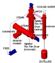
Mechanically Agitated Thin Film Dryer is an indirectly heated continuous dryer. The feed can be in the form of a solution, slurry, wet cake or paste. If required, it operates under vacuum. We offer both vertical and horizontal versions.
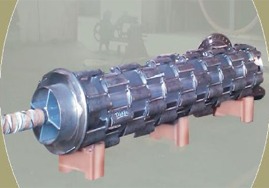
How they work :
The vertical Agitated Thin Film Dryer has a jacketed cylinder with a closely fitting rotor at the centre. During operation, the rotor revolves at high speed. The feed distributor spreads the incoming feed uniformly over the cylinder top periphery. The rotor blades pick up the material, spread it over a heated surface in a thin film and agitate the film intensely, as it rapidly travels down. The material transforms from solution to the slurry, wet cake, wet powder and finally dry powder as it travels from top to bottom. The vapour generated rises counter-currently to the inbuilt entrainment separator. Here the entrained droplets are separated from the vapour stream. The clean vapour leaves the dryer through the vapour nozzle at the top.
The horizontal version of the dryer is used for drying of wet cake, pastes, wet powders. The wet feed enters at one end and dry powder leaves from the opposite end. The vapours move counter currently to the powder flow and leave through vapour nozzle.
Features :
• Feeds can be processed without pre-concentration or dilution
• Indirect heating and drying in the absence of air. Particularly effective for heat, light and oxygen sensitive products. Best suited for solvent bearing products for complete solvent recovery
• Quick processing time, best suitable for heat sensitive products
• Probably the most energy efficient dryer in the market. Thermal efficiency exceeds 90%
• Fine powder of uniform consistency can eliminate pulverizer from downstream step
• Intense agitation suppresses fouling, keeps heat transfer surface clean
• Operating pressure under vacuum, up to 1 torr
• Excellent turndown capability
• Low product holdup, ideal for hazardous applications
• Different rotor configurations to suit variety of applications
Applications :
Drying
• APIs, bulk drugs, and intermediates
• Dyes, pigments, and intermediates
• Organic and inorganic salts
Recoveries
• Solvent and products from thick dry residues
• DMSO from salt bearing organic residues
• Glycerine from salt bearing organic residues
• Water from organic and salt bearing waste water streams
Jacketted Pipe Heat Exchanger
In double pipe heat exchanger design, an important factor is the type of flow pattern in the heat exchanger. A double pipe heat exchanger will typically be either counterflow or parallel flow. Crossflow just doesn’t work for a double pipe heat exchanger. The flow pattern and the required heat exchange duty allows calculation of the log mean temperature difference. That together with an estimated overall heat transfer coefficient allows calculation of the required heat transfer surface area.
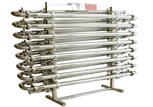
A double pipe heat exchanger, in its simplest form, is just one pipe inside another larger pipe. One fluid flows through the inside pipe and the other flows through the annulus between the two pipes. The wall of the inner pipe is the heat transfer surface. The pipes are usually doubled back multiple times as shown in the diagram at the left, in order to make the overall unit more compact.
Thermal Capability
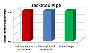
Since the heating medium is in direct contact with the entire process pipe surface area, jacketed pipe provides maximum heat transfer to the process. Heat transfer to the process is only limited by the process convection coefficient. For these reasons, jacketed piping possesses the maximum thermal capability for bulk temperature maintenance, wall temperature maintenance, and heat exchanger applications (including melt out).
Applications :
• A primary advantage of a double pipe heat exchanger is that it can be operated in a true counterflow pattern, which is the most efficient flow pattern.
• It will give the highest overall heat transfer coefficient for the double pipe heat exchanger design.
Advantages :
• Double pipe heat exchangers can handle high pressures and temperatures well.
• When they are operating in true counterflow, they can operate with a temperature cross.
• The cold side outlet temperature is higher than the hot side outlet temperature
Limpetted Reactor / Jacketted Reactors
Stirred tank agitated reactors are commonly used in Process Industries and consist of a mechanical agitator and a cooling jacket or coils. They are operated as batch reactors or continuous reactors.
Several reactors may be used in series. The stirred tank reactor can be considered the basic chemical reactor; modeling on a large scales the conventional laboratory flask. Tank sizes range from a few liters to several thousand liters. They are used for homogeneous and heterogeneous liquid-liquid and liquid-gas reactions and for reactions that involve freely suspended solids, which are held in suspension by the agitation. As the degree of agitation is under the designer’s control, stirred tank reactors are particularly suitable for reactions where good mass transfer or heat transfer is required.
When operated as a continuous process the composition in the reactor is constant and the same as the product stream and except for very rapid reactions, this will limit the conversion that can be obtained in one stage
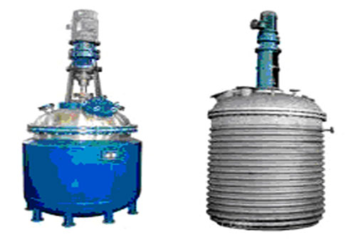
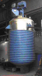
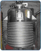
Limpet Coil Reactor construction is same as of the Jacketed Reaction vessel except instead of Jacket on the Shell of Reaction vessel Limpet Coil is welded on it. LimpetCoil Reaction Vessel consists of a Cylindrical vertical shell with a standard torospherical dish on both ends.
Limpet Coil is Half round Pipes welded on the outer surface of the shell and also in the bottom dish of the Limpet Coil Reaction Vessel.
Limpet coil vessel’s limpet coil is made of either Mild Steel Or Stainless Steel. It is either Double end double start for both heating and cooling through limpet coil or Normal Single coil for either heating or cooling. Limpet Coil Welding is performed by using high grade filler rods depending on MOC of the Limpet Coil to withstand design pressure.
We offer high quality Limpet Coil Reaction Vessel in different capacities ranging from 50 liters to 15,000 liters.
Fabricated from superior grade of stainless steel, these vessels can be provided with different types of agitators such as anchor type, propeller type, paddle type, pitched blade turbine type of high-speed homogenizer. The unique design of our reaction vessels to allow the conditions to be controlled for fastest possible chemical reaction.
We are offering Chemical Reactors with the following features:
• High durability and reliability – Less maintenance require
• Resistant to corrosion and temperature fluctuations Safe to use
• Available in various specifications
• Made up of best grades of materials
• Better efficiency
• Technically advanced
• Rust proof
• Corrosion resistant
Contact Us At
Address
Paramount Limited, Paramount Complex, Near Natubhai Circle, Race Course, Vadodara, Gujarat - 390007
Phone Number
Vadodara: +91-0265-2397111 (7 lines)
New Delhi: +91-11-26186525, 26186369
Mumbai: +91-22-24073108, 24078105
Email Address
Vadodara: sales@paramountlimited.com
New Delhi: delhi@paramountlimited.com
Mumbai: mumbai@paramountlimited.com

